STANDING WAVE RATIO METER (SWR) FOR "ATV" 23c/m
I was checking the New Repeater Alford Slots for GB3FY and my own TX for matching trying to get the best RF out of the system but ALAS I had nothing that seemed to work and give me a correct reading with reference to the forward and reverse power readings. I have SWR's up to 500MHz but they did not work correctly at all on 1255MHz. So I decided to build one and this opened a can of worms and a long learning curve of things to do and not do.
NOTE I have an SWR at 10GHz............ HI but a complex one.
The first problem was I had no known RF small signal diodes. Farnell had some suitable types with low volts drop and low capacitance.
I looked at several designs and built them with poor results.
I read every CQ-TV mag and other RSGB books but I felt there was something missing and after 3 days and 4 PCB layouts found something that worked well and was not upset by holding the current leads coming from the unit to the meter. I also found out by trial and error a lot of published designs are actually wrong.
The two pickup points must be done at the same point near the 50 ohms strip line. Because as you move along the line the wave changes level.
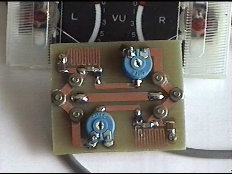
I used small SMA sockets not big "N" types to keep the PCB small and less trouble but I did find that the fixing screws upset the reading because they was very close to the 50 ohms stipline. After careful thought I turned these by 45 degrees and left one screw out and found 3 screws was holding the socket very well. By adding track to the 3 screws and other earthy components gave us a shielding ground plane around the outer parts of the circuit. I used Surface Mount components (SM) to stabilize design and performance and worked well. I was going to fit ferrite beads in series with the DC forward and reverse lines to isolate the DC and RF side but instead I made a PCB Coil as big as would fit in the spare area I had left.
So by placing the pickup coils on either side of the 50 ohms Stipline and making every thing small plus moving the diode and the termination resister near to the pickup line not bringing line back at right angles to the main line produced very good results.
One other thing I was frustrated by was that in 90% of articles never told you how to set it up but an article in CQ-TV by John Stockey G8MNY did worth reading it's Number 162 May 1993........
METER SCALE
Deflection % 100 80 72 50 33 20 8 0
SWR 1: Inf 9 6 3 2 1.5 1.2 1
Loss dB Inf 4.4 3 1.3 0.5 0.2 0.35 0
Size is just 47mm by 40mm on the other side is just 2 off SMA sockets
Need a tin can on it yet!
It has started me thinking now I know a little more that it is possible to make a PIC based unit that told you the LOAD Z and POWER and the FORWARD and REVERSE readings by adding DIGITAL controlled pots !........If I ever get the time but the Repeater and Aerials are at the top of the list todate..
Don't forget just £5 to join the FYLDE ATV
GROUP send to DAVE G8KBH.....QTHR..