Electronic Antenna Rotator Controller
10 to 16 Pre-Positions
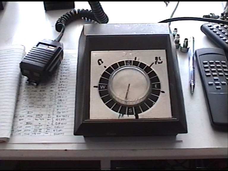
While operating ATV and peaking up the very last once of signal it soon becomes clear after working several stations in the same period that an accurate method of positioning the antenna would help.
I used to have one years ago and put little pegs in and could get up to 10 pre-set aerial headings.
Well with the growing local activity I sat and thought of the easiest and cheapest way to do it without a lot of mechanical pots and things connected to the rotator. So it can be done on the ground. KISS
Mine is an EL CHEEPO unit (CHANNEL MASTER) that is turned by a 2 phase system and the bottom unit relies on the phases operating both units in sync...Very noisy YER YER YER YER YER YER in the shack.
Well we need a Display 4 Digit and a pair of clockwise and anti-clockwise buttons also three buttons to set the pre-positions up to 10 or more can be programmed in. One of the digits will show the pre-position 0-F(16)
The Display is the usual 2 wire drive type LED just clock and data and on the 36th clock the data is in parallel transferred to the 4 x 7 segment LED's and the decimal points too.
So the simple task is done by a 18 PIN PIC16F84 with 64 bytes of e2 memory so it remembers on switch off/on.
Just 2 little relays so the PIC can control the power and phase to the rotator. Software makes sure BOTH relays cannot be on at the same time even if you hold all buttons in.
All the PIC has to do is count up or down depending on the request. And work out the pre-position direction when selected and save any changes ONLY when needed.
My unit took 77 seconds to do a not fully 360 Degs.....Quick guess is that 11 cycles of 50hz mains gives rise to 1 Deg of rotation in total 3960 pulses per 360 Degs of rotation.
So a DIV by 11 up/down counter is required and 3 decade up/down counters is required.
And a 3 Digit Comparator to work out the pre-position Direction and Equality.
Three MODE buttons were required to switch between preposition number and learn/save functions.
I already have a Display Function I use on all my RX's and TX's so it's just Copy and Paste about 3mins of a job then assign the port bits to send out the serial data. Also the e2 save and restore routines. Actually the software took three days HI.
Software problems will be to get it to north and Zero the Display but that can be done by zeroing the count and turning the rotator anticlockwise for at least 80secs till it hits the limit switch. Once done the e2 memory will keep track of it from then on.
The PCB is very small the biggest thing will be the AC PSU for the rotator.
During Development we blew up the small relays (not has shown) ruined 2 PIC's due to writing to the E2 millions of times when no button was pressed and experienced for the first time writing to the E2 and having external interrupts working in a NO go situation it just locks up ! All Good Fun....now sorted....and no noise XYL is suited...
The only side effect noticed was that a slight amount of start up and stop digits is noticed after a long period of use.
I think that this error can be offset once I get chance to work out the real values. It's mechanical START and STOP slip delays.
Above is before and below is after
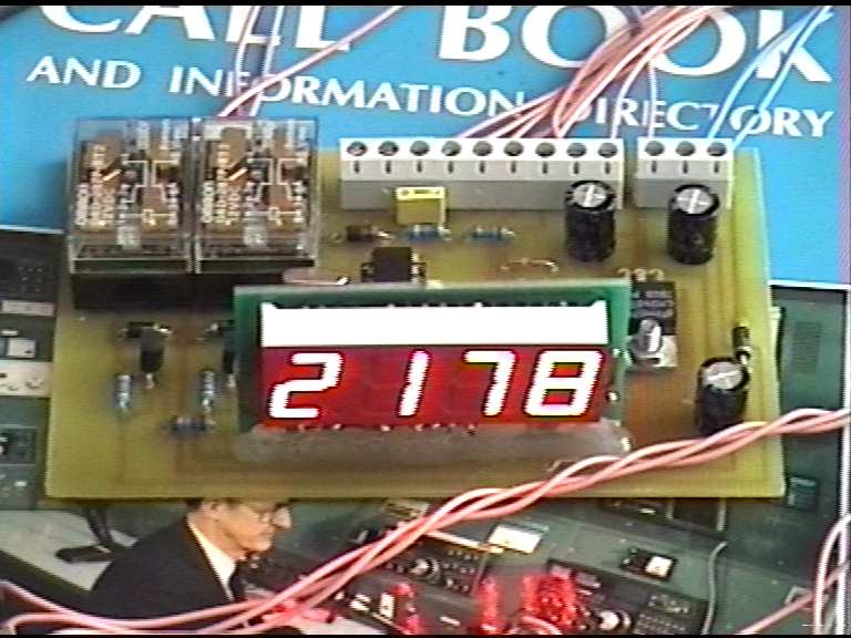
Digit 1 on the left is the Pre-position Number (2) and the rest is the direction
178 Degs in the example beaming at G0HIU at Lytham
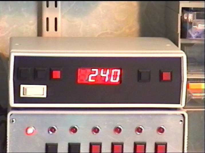
The Channel number (left) blanks out after a few seconds to leave just the degrees
The unit is pointing to GB3TM on 1316MHz ATV repeater
The Lower unit is my TX Vision and Sound Controller (OFF).

This will retrofit onto most 2 phase units (C)